
This is an old revision of the document!
Table of Contents
De diepte regelneus en de freesstand calibreren
Als de diepte van een graveerfreesje niet mechanisch beperkt zou worden, zou het zich gewoon door het graveermateriaal in de graveertafel boren. Om ervoor te zorgen dat het freesje op een welbepaalde diepte in het materiaal graveert, moet de Z-as beweging beperkt worden.
Dat kan op de volgende twee manieren:
- Ofwel wordt de exacte omlaag beweging van de spindel geregeld;
- ofwel wordt een mechanische dieptebegrenzing gebruikt. deze methode is veruit de gemakkelijkste. Daarvoor is elke Cyborg graveermachine uitgerust met een diepte regelneus.
In dit hoofdstuk wordt de werking van de diepte regelneus uitgelegd. De diepte regelneus wordt gebruikt om de gewenste graveerdiepte in je materiaal in te stellen. het is de gemakkelijkste en veiligste manier om een constante graveerdiepte te bekomen in de meeste graveermaterialen.
Later wordt meer in detail uitgelegd hoe de machine kan gebruikt worden zonder diepte regelneus, d.m.v. een vooraf ingestelde graveerdiepte via het virtuele toetsenbord van de machine.
Calibratie van de diepte regelneus
We beginnen met de machine hoofdschakelaar aan, maar geen frees met spanknop in de spindel.
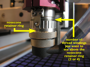 De afbeelding links toont hoe de neusconus houderring in te stellen. Draai deze ring zo dat je erboven 3 tot 4 draadomwentelingen ziet.
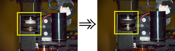 Vervolgens draai je de veerdrukring helemaal omhoog, zoals getoond op de tweede afbeelding links hiernaast.
Nota: If your spring pressure ring remains in its lowest position, the machine’s Z-axis floating system is locked. Not only will you be unable to go through the remainder of this calibration procedure, but the machine won’t be able engraving at a constant depth using the nosecone. Place a metal plate, e.g. a piece of anodized aluminium, underneath the spindle on your table surface and push the Z-down key on your virtual pendant until the nosecone rests on the metal plate. Once the nosecone is touching the metal plate, stop pushing the Z-down key.
Screw a brass cutter knob counterclockwise into the spindle.- You will notice that the thread of the cutter knobs is always negative to make sure they don’t come loose while the spindle rotates. Tighten the cutter knob firmly, but only by hand.
Note: There is no need to use pliers to do so. Using pliers may damage the cutter knob thread or even destroy it. - When the cutter knob is firmly tightened into the spindle, gently slide a cutter through the hole in the cutter knob and push it all the way down until it touches the metal plate under the spindle.
- Using your cutter knob wrench, tighten the cutter knob on the cutter. The cutter nows sits tightly fixed in its knob, with its tip exactly parallel at level with the bottom of the depth regulator nose.


Calibrating the cutter stand
If you intend to use the cutter calibration stand, you will now have to calibrate it so that the cutters which are calibrated in the stand all get an equal setup which fits the spindle length. The purpose is to make sure that swapping tools automatically results in exactly the same engraving depth. Let us walk you through the procedure to adapt the calibration stand to the engraving spindle’s length.
Continue to use of the depth regulator nose.
Continue to the table of contents.


