
This is an old revision of the document!
Table of Contents
Utilisation du ressort de pression

Verrouillage du ressort de pression pour gravure sans nez régulateur de profondeur
Si vous souhaitez graver sans nez, par ex. après avoir réalisé une topographie de surface, ou lors de la découpe d’un relief 3D, l’anneau de pression à ressort doit être verrouillé. Pour verrouiller cet anneau , il doit être complètement vissé vers le bas.
 Cette image montre la bague de pression de la broche en position haute (déverrouillée).
 Cette image montre la bague de pression de la broche en position basse (verrouillée).
| Note: Soyez extrêmement prudent de ne jamais utiliser le nez de votre broche lorsque la bague de verrouillage du ressort est abaissée. Vous pourriez endommager votre moteur de l’axe Z, la vis sans fin de l’axe Z et même la commande numérique. En d’autres termes, respectez toujours le principe suivant : Ne lancez jamais un cycle de gravure en utilisant à la fois le nez de la broche et la bague de blocage du ressort de pression vissée. |
Surfaçage de plaque avec ressort déverrouillé et gravure avec ressort verrouillé
Dans la section ci-dessus, vous pouvez lire comment verrouiller la bague du ressort et comment retirer le nez palpeur.
Pour surfacer puis graver sans nez, vous procédez comme suit :
- Visser la bague de blocage à pression du ressort jusqu’en haut, déverrouillant ainsi le mouvement flottant.
- Retirez le tuyau d’aspiration transparent du pied d’aspiration.
- Retirez l’anneau qui retient le nez avec le pied d’aspiration.
- Insérez la fraise que vous souhaitez utiliser dans la broche et serrez-la.
- Placez votre matériau à graver sur la table de gravure et assurez-vous qu’il soit bien fixé.
- Déplacez la broche quelque part sur la plaque à graver.
- Assurez-vous que la « plate surface » indique
 . Sinon, activez ce mode en cliquant sur la touche .
 - Cliquez sur la touche « définir la surface du matériau »
 sur votre clavier.
 - Cliquez sur le bouton « probe »
 pour commencer la routine de surfaçage. Continuez à appuyer sur cette touche « probe » et l’axe Z descendra lentement jusqu’à ce que la broche touche le matériau. Il remontera alors au-dessus de la surface du matériau.
 - La procédure mentionnée ci-dessus implique que votre fraise touche votre matériau de gravure. Si vous préférez que cela n’arrive pas, en raison du risque potentiel d’endommager votre plaque, vous pouvez utiliser une plaque fine entre les deux, dont vous connaissez l’épaisseur exacte. Gardez à l’esprit que l’épaisseur de cette plaque factice doit être ajoutée à la profondeur de votre gravure pour obtenir la bonne profondeur.
- Vissez l’anneau de verrouillage du ressort vers le bas, afin que le mécanisme flottant soit complètement verrouillé.
- Exécutez votre travail de gravure.


Notes:

- En travaillant sans nez et avec un mécanisme flottant verrouillé, la machine exécutera les profondeurs qui se trouvent dans le travail de gravure. Si votre travail de gravure contient des profondeurs, cela dépend entièrement du logiciel utilisé. Certains logiciels utilisent des instructions de profondeur Z et de Z-vers-le-haut, d’autres logiciels utilisent simplement une instruction « Fraise bas » et une « Fraise haut », sans spécifier de valeur réelle. Dans ces derniers cas, la machine utilisera une profondeur préprogrammée, qui peut être saisie ou modifiée via la « fenêtre de dialogue Job » sur le clavier virtuel.
- Les valeurs qui sont spécifiées dans la « fenêtre de dialogue du travail », ne seront utilisées que si le travail de gravure ou de fraisage en question ne contient pas de valeurs pour ces variables spécifiques. Ceci est valable variable par variable. Par exemple, si le travail de gravure ne contient pas de profondeurs, mais contient bien des vitesses XY, alors le système utilisera la profondeur spécifiée dans la « fenêtre de dialogue du travail », mais le paramètre de vitesse XY dans le travail annulera automatiquement le paramètre de vitesse XY qui est visible dans la « fenêtre de dialogue de travail ».
Topographie de surface avec ressort déverrouillé et gravure de surfaces inégales avec ressort verrouillé
If the object you want to engrave has an irregular surface, or if the plate you want to engrave is cast acrylic (PMMA), which can have rather important differences in thickness, and you do not want to use the nosecone because of the risk of scratches or shadows along the engraved characters, then using the surface mapper is a possible solution. Surface mapping a plate surface works as follows:
- Remove the engraving cutter from the spindle.
- Remove the vacuum hose from the spindle and then remove the nosecone retainer ring with the nosecone and the vacuum boot from the engraving spindle.
- Insert the special surface map rod (option) into the spindle and fix it in the cutter knob when the rod sticks about 10 mm out at the bottom of the spindle.
- Make sure the spring pressure lock ring is in the max up position.
- Position your object to be mapped on the engraving table and secure it.
- Position your spindle in the upper left corner of an imaginary rectangle in which the engraving job has to be executed. This imaginary rectangle is not necessarily the same as the object’s surface, it can be smaller (but not bigger), and set home there.
- Make sure the “plate surface” is set to
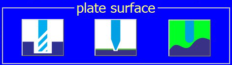 .
. - Then click the “set surface” key, which will make a small window pop up. In this window several variables have to be entered:
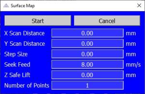
- * “X scan distance”: the width of the imaginary rectangle you want to map. Entering values has to be done by typing the correct numbers on your computer’s keyboard.
- “Y scan distance”: the height of the same imaginary rectangle you want to map.
- “Step size”: the distance between each of the points to be digitized, both in X and in Y. If your plate is almost flat and has relatively unimportant height differences, you can use a relatively high value, e.g. 20 or even 30 mm. If your object has a more irregular relief, keep the step size small, e.g. 5 mm. Which value you have to choose with which kind of surface is a matter of trying and building some experience.
- “seek feed”: the speed at which the spindle with the mapping rod will move down to map each of the points in the mapping matrix. Normally a speed between 5 and 15 mm/sec is adequate.
- “Z Safe Lift”: Z-up move after mapping each point. You just have to make sure that the lift value is high enough to move over to the next point. Suppose that the relief has a rather steep surface, and that the Z-position of the next point to be measured is 3 mm higher than the last measuring point. It is clear that your Z safe lift has to be bigger than 3 mm, otherwise your mapping rod will crash sideways with your relief.
- “save surface map”: In normal circumstances you do not want to save the surface map unless you have to engrave a series of objects with identical surfaces. If you want to save a mapped surface, highlight the “Save Surface Map” option and click the “Enter” key.
There is a separate chapter in this manual, where you can read in detail about the surface mapping option.
- Take out the mapping rod from the spindle, put in the engraving cutter of your choice, surface the cutter somewhere inside the imaginary rectangle which has been mapped and run your engraving job.
- Your 2D engraving job, with all of its speeds and depths, will be projected on the mapped surface. The mapped surface is a fluid interpolated cloud of points. Although the machine in reality performs a 3d job, for the user it is just a 2D application.


Continue to speeds and feeds for different materials.
Continue to the table of contents.


