
This is an old revision of the document!
Table of Contents
Calibrage du nez palpeur et du support de calibrage de la fraise
Les outils de gravure ou les fraises, lorsqu’ils ne sont pas limités dans leur mouvement vers le bas (axe Z), graveront directement à travers la plupart des matériaux de gravure en plastique, bois et métal. Afin de s’assurer que la fraise cesse de plonger dans le matériau et effectue sa coupe à une certaine profondeur prédéterminée, que nous appelons la profondeur de gravure, nous devons limiter le mouvement de la fraise sur l’axe Z..
Nous pouvons faire cela de deux façons:
- soit nous créons un travail spécifiant un mouvement exact de l’axe Z (la broche);
- soit nous trouvons un moyen mécanique de limiter la profondeur de gravure, même si le mouvement de l’axe Z a été réglé différemment. Spécialement à cet effet, les machines Cyborg sont équipées d’un nez palpeur qui limite la profondeur.
Dans ce chapitre, nous expliquerons comment utiliser le nez palpeur. Le plus souvent, vous souhaiterez utiliser le nez palpeur pour régler la profondeur de gravure sur votre machine. C’est le moyen le plus simple et le plus sûr d’obtenir une profondeur de gravure constante pour la grande majorité des matériaux.
Plus tard, nous expliquerons en détail comment utiliser la machine sans le nez palpeur, en utilisant une instruction prédéfinie de l’axe Z via le panneau de commande de la machine.
Calibrage du nez palpeur
We start with the machine turned off, and with no cutter or cutter knob placed in the spindle.
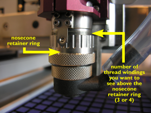 The picture to the right shows how to set the nosecone retainer ring on the spindle. Screw or unscrew this ring so that you will have about 3 to 4 thread windings visible above the nosecone retainer ring.
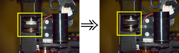 Next, screw the black knurled spring pressure ring all the way up, as shown in the image on the right.
Note: If your spring pressure ring remains in its lowest position, the machine’s Z-axis floating system is locked. Not only will you be unable to go through the remainder of this calibration procedure, but the machine won’t be able engraving at a constant depth using the nosecone. Place a metal plate, e.g. a piece of anodized aluminium, underneath the spindle on your table surface and push the Z-down key on your virtual pendant until the nosecone rests on the metal plate. Once the nosecone is touching the metal plate, stop pushing the Z-down key.
Screw a brass cutter knob counterclockwise into the spindle.- You will notice that the thread of the cutter knobs is always negative to make sure they don’t come loose while the spindle rotates. Tighten the cutter knob firmly, but only by hand.
Note: There is no need to use pliers to do so. Using pliers may damage the cutter knob thread or even destroy it. - When the cutter knob is firmly tightened into the spindle, gently slide a cutter through the hole in the cutter knob and push it all the way down until it touches the metal plate under the spindle.
- Using your cutter knob wrench, tighten the cutter knob on the cutter. The cutter nows sits tightly fixed in its knob, with its tip exactly parallel at level with the bottom of the depth regulator nose.


Calibrating the cutter stand
If you intend to use the cutter calibration stand, you will now have to calibrate it so that the cutters which are calibrated in the stand all get an equal setup which fits the spindle length. The purpose is to make sure that swapping tools automatically results in exactly the same engraving depth. Let us walk you through the procedure to adapt the calibration stand to the engraving spindle’s length.
Continue to use of the depth regulator nose.
Continue to the table of contents.


