
This is an old revision of the document!
Table of Contents
Calibrating the depth regulator nose and the cutter calibration stand
Engraving tools or cutters, when not limited in their downward (Z axis) movement, will engrave straight through most plastics, wood and metal engraving materials. In order to make sure the cutter stops plunging into the material and makes its cut a certain predetermined depth, which we call the engraving depth, we have to limit the Z axis movement of the cutter.
We can do so in two ways:
- either we create a job specifying an exact Z axis movement of the spindle;
- or we find a mechanical way to limit the engraving depth, even if the Z axis movement has been set differently. Specifically for that purpose, the Cyborg machines are equipped with a depth regulator nose.1)
In this chapter, we will explain how to use the depth regulator nose. Most often, you will want to use the depth regulator nose as a means to set the engraving depth on your machine. It is the easiest and most secure way to obtain a constant engraving depth for the large majority of materials.
Later on we will explain in detail how to use the machine without the depth regulator nose, using a predefined Z axis instruction set through the machine’s control panel.
Calibrating the regulator nose
We start with the machine turned off, and with no cutter or cutter knob placed in the spindle.
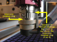 The picture to the right shows how to set the nosecone retainer ring on the spindle. Screw or unscrew this ring so that you will have about 3 to 4 thread windings visible above the nosecone retainer ring.
 2) Next, screw the black knurled spring pressure ring all the way up, as shown in the first image.
Note: If your spring pressure ring remains in its lowest position, the machine’s Z-axis floating system is blocked. Not only will you be unable to go through the remainder of this calibration procedure, but the machine won’t be able engraving at a constant depth using the nosecone.
 Place a metal plate, e.g. a piece of anodized aluminium, underneath the spindle on your table surface and push the Z-down key on your virtual pendant until the nosecone rests on the metal plate. Once the nosecone is touching the metal plate, stop pushing the Z-down key.
{afbeelding} {afbeelding}- Screw a brass cutter knob counterclockwise into the spindle.
You will notice that the thread of the cutter knobs is always negative to make sure they don’t come loose while the spindle rotates. Tighten the cutter knob firmly, but only by hand.
Note: There is no need to use pliers to do so. Using pliers may damage the cutter knob thread or even destroy it.
- When the cutter knob is firmly tightened into the spindle, gently slide a cutter through the hole in the cutter knob and push it all the way down until it touches the metal plate under the spindle.
- Using your cutter knob wrench, tighten the cutter knob on the cutter, as shown in the image above on the right. The cutter nows sits tightly fixed in its knob, with its tip exactly parallel at level with the bottom of the depth regulator nose.


Calibrating the cutter stand
If you intend to use the cutter calibration stand, you will now have to calibrate it so that the cutters which are calibrated in the stand all get an equal setup which fits the spindle length. The purpose is to make sure that swapping tools automatically results in exactly the same engraving depth. Let us walk you through the procedure to adapt the calibration stand to the engraving spindle’s length.
- Taking the cutter knob between thumb and index, unscrew the cutter knob with the cutter in it from the spindle and pull it out.
Remember: The screw thread on the knob is left-handed, so in order to unscrew it, you have to rotate it clockwise.
- After having screwed down the knurled cylinder head set screw with the knurled cylindrical nut (see image below), insert the cutter with cutter knob in the cutter stand and tighten counterclockwise by hand. Do not use pliers!
- In the first image3) below you can see the screw and nut all the way down. Move the screw and nut up to the point where the flat cylindrical surface of the screw touches the tip of the cutter (middle image). Finally, while keeping the screw in that position, screw the locking nut all the way down and tighten it by hand (3rd picture). The cutter stand calibration length and the spindle length have now been set equal.
You can now use the position of the screw as a reference for all other engraving cutters by placing a cutter knob in the stand, sliding a cutter through the hole, and tightening the cutter knob on each cutter at the exact same height.


